Biggied
They called him mellow yellow.
- Joined
- Feb 23, 2006
- Messages
- 198
- Reaction score
- 3
- Points
- 18
- Location
- Scotland
- Website
- www.audi.co.uk
First of all I'd like to say well done on the Build/Thread mate, the best I've followed in a long time.
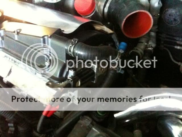
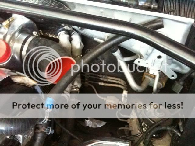
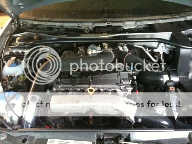
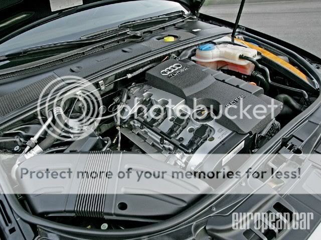
I'm loving the finish & detail your putting into the engine bay, job well done. Now you may already be aware of these or it may not be any use now that you've made your new coil pack heat sheild but, have you seen the coil pack loom covers from the 2.0T A4's (as pictured bellow) There also available in red from none turbo FSI A4's but I thot I'd fire up a pic of the black one as this seems to be your favored colour for the bay. Not that the stock foil/fiber effort dosn't do its job just thot this would suit your needs better.
once again cracking job your doing there mate, keep it up. Ewan.
")