

- Joined
- Nov 23, 2008
- Messages
- 724
- Reaction score
- 81
- Points
- 28
Welcome to my attempt at showing you how to retro fit heated mirrors to the Audi A1.
My car is the A1 1.4 TFSI 185(PS) Black Edition. It is I believe a MY2012 edition.
It did not come with heated mirrors!
WARNING!! All modifications and changes are done at your own risk. I in no way approve or recommend the modifications performed here for your vehicle. Please check with your dealer or other competent person before performing any changes to your car as they may void portions of your factory warranty.
This âhow toâ is how I did it successfully, your car may be different and may have different part numbers and fittings. If you follow these instructions you do so at your own risk. I will not be held responsible for any damage done to your car should you follow this thread and damage your car. This is my story! Treat it purely as it is intended, a written record of what I did. Before prizing any plastic parts away from each other I suggest taping them up with masking tape to avoid unnecessary scratches and marks.
For info, the part numbers for my door control modules are:-
8X0 959 793 Dâ Drivers door
8X0 959 792 Dâ Passenger door
This info can be found by doing a VCDS scan
Tools required
T25 Torx Screwdriver
T10 Torx Screwdriver
10mm socket, wrench with extension bar
Small Phillips screwdriver
Small Slot Screwdriver
Medium Slot Screwdriver
Wire Cutters
Soldering Iron
Wide chisel
Masking tape
Cloth Tape
Cloth
VCDS
Parts
Left and right mirror glass with heating element. (Various mirrors available for approx £25-£30 each)
Yellow Repair wire (part number U000 979 009)
4 metres of thin wall wire
I used thinwall cable from:-
http://www.vehicle-wiring-products.eu/VWP-onlinestore/cable/thinwall.php
2 x 6mm female blade terminals like :-
http://www.vehicle-wiring-products.eu/VWP-onlinestore/terminalsnonins/noninsblades.php
Heat shrink from:-
http://www.vehicle-wiring-products.eu/VWP-onlinestore/sleeving/heatshrink.php
The retro-fit
Lower window down.
Ensure that ignition is off and remove key.
Both doors are essentially the same.
1. Remove Door card.
Gently prize off the speaker grill. On my car this was a blank. I applied masking tape to both the surround and the speaker grill to avoid damage to the plastic.
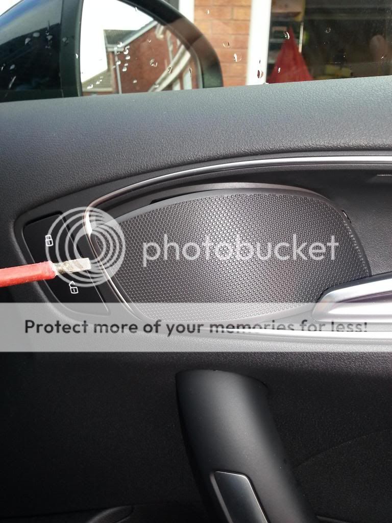
Then gently prize of the front piece of the door handle. Again cover both pieces with tape to avoid damage.

On removal of the speaker grill and door handle it will expose a Torx bolt behind each of them.

There are 4 Torx bolts to remove in all, numbered 1 â 4 in the photograph below. Use a T25 Torx bit.

You will then need to prize the door card away from the door itself. You may need to insert a chisel in between the door card and the door and lever it off until the poppers behind pop (as shown circled in yellow in the photograph shown a couple of steps below) or you might as I did manage to lever off with your fingers. If you use a chisel, wrap it in a cloth and use tape to avoid damage. Once the door card is off it will remain attached to the door by the cable operating the door handle opener and a wiring loom going direct to the door control module.
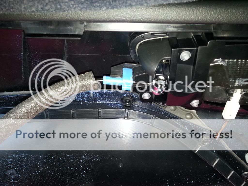
With regards to the cable for the door handle, prize off the blue clip, rotate the cable 90 degrees and lift it away. (Hard to explain but easy when seen).
The door control module
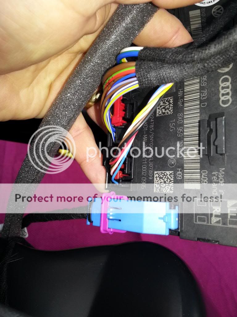
To separate the wiring loom from the door control module, lift the purple clip up (it will swivel) and then the light blue plug will lift away as the purple clip rotates.
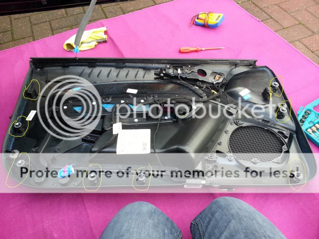
The door card is now free. I placed it upside down and you can now see the 8 poppers circled in yellow which pop into the door in the picture above. These will likely break so it may be handy to buy some spares.

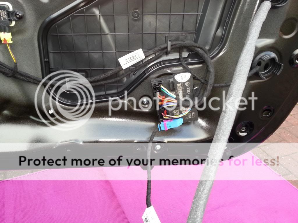
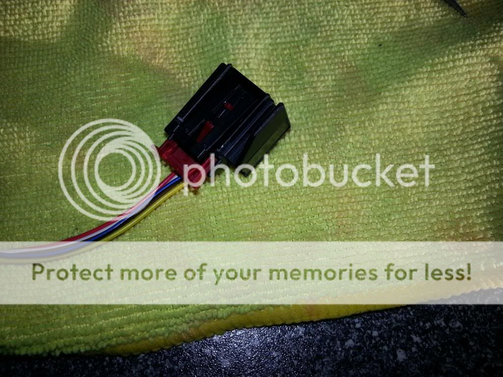
Next remove the plug that I have shown by a white spot on the photo above. (Although covered by the white spot, it can be seen clearly in prior photo. You will need to lift the red clip up first and then lever out. This is the 16 pin plug which I will refer to later and connects the wiring loom of the mirror to the door control module.
I decided to remove the whole wing mirror from the door. The cabling should be easily seen and followed between the mirror housing and the 16 pin plug. Remove this wire so that's its free all the way up to the mirror. Remove the three grommets from the door as shown in photo below:
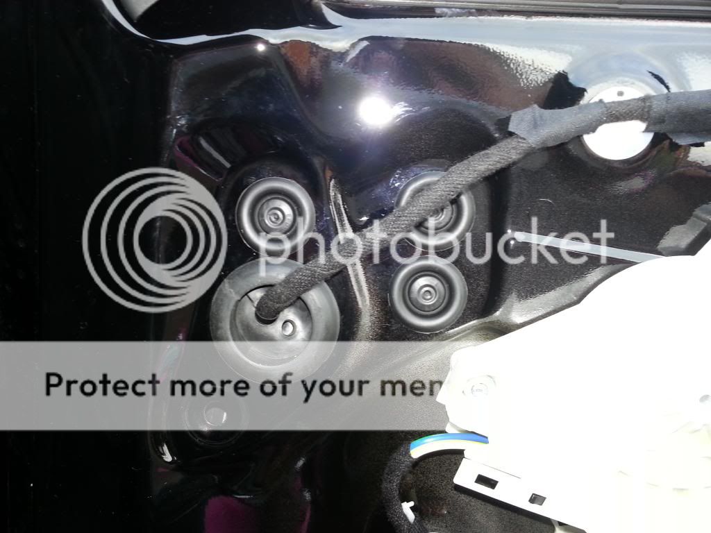
Then pull out the large grommet where the wiring looms goes through.
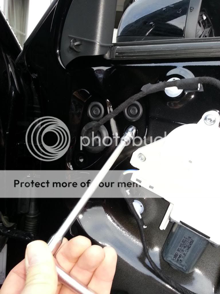
Insert a 10mm socket on an extension bar into one of the 3 holes and remove the nut holding the mirror to the door. All 3 need doing in the separate holes. (this is why the window needs to be down).
There are some nylon ties holding the wiring loom inside the door which will need to be removed or cut. This was quite difficult to do, so I ended up cutting them. Be careful when removing the nuts as they are easy to drop into the inside of the door. You will then need to remove the large door speaker below to get them.
The mirror should then come away from the door. Feed the cable through the hole and remove mirror assembly away completely.

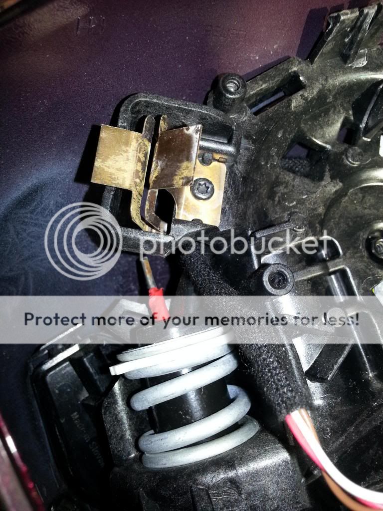
Remove the mirror glass from the mirror housing. Angle the mirror glass upwards, insert awide chisel in between mirror glass and mirror body (wrapped in a cloth) and prize mirror glass away. This needs a bit of force but be very careful. Too much force in a small area will crack the glass. You may be able to use yourfingers. It takes a bit of toing and froing, but the mirror glass will eventually come out.
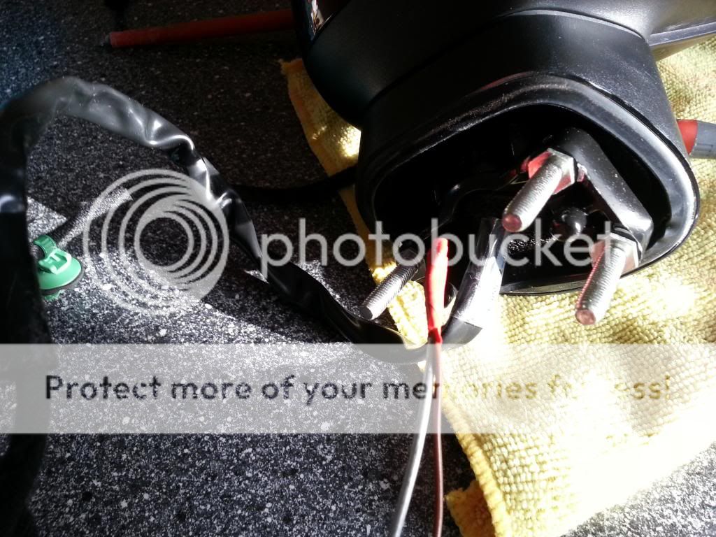
Using a T10 Torx bit, unscrew the 4 screws holding the inner mirror body to the outer mirror body. Also undo and remove the screw in the centre of the mirror motor. All 4 screws and mirror motor screw are shown coloured by the 5 purple dots in the next photograph.

Insert afairly wide flat screw driver at the top of the mirror and twist the clips so that the inner mirror body and outer mirror body separate. You will also need to apply a pit of leverage between the two plastic bodies to ease them apart at the same time.


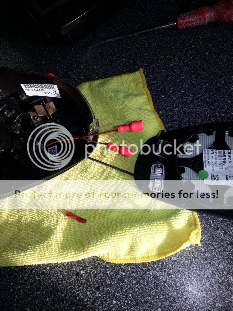
Feed two pieces of wire from the bottom of the mirror housing through the mirror body shown in the photo below. I used a coat hanger with the wires taped to the end (Don't go through the foam sponge, aim to go at the side). Push and wiggle until the coat hanger comes out the top above the spring shown. See pictures below.

Pull wire through mirror body, strip the ends of the wires and crimp onto the ends the two female spade connectors.
Re-assemble the mirror casing/body in the reverse way you took it apart. Push on the two female spade connectors onto your new heated mirror glass and then push and clip the mirror glass back into its housing. The two long (finger type) pieces of plastic need to be guided into the two âbronzeâ type oblong clip holders shown in the photos above. The mirror glass should just snap back into its clips. Apply even pressure and again be careful not to crack it.
Tape the two new wires to the remainder of the wiring loom all the way down to the 16 pin plug.
The 16 pin plug has inserts for 16 wires and these inserts are all numbered.

With a small flat headed screwdriver lift up the small clip on the side of the 16 pin plug gently and slide out the inner body.

A Picture of a repair wire is shown below on top of the wiring diagram for the mirrors. Ignore the purple/black writing in pencil, this is the colour of the wire found in the loom of a car with heated mirrors already.
Cut the repair wire in half and insert one end into the pin marked number 15 on the 16 pin plug. Solder the other end of this repair wire to one on the new wires going to the new heated mirror glass. Use heat shrink wrap to protect the soldered joint and tape this to the existing mirror wiring loom.
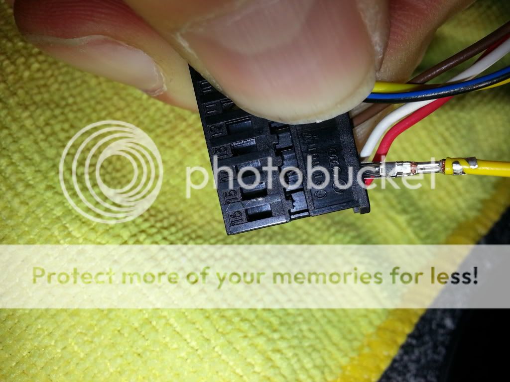
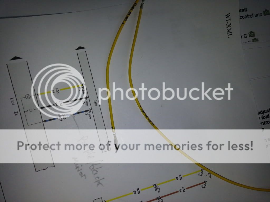
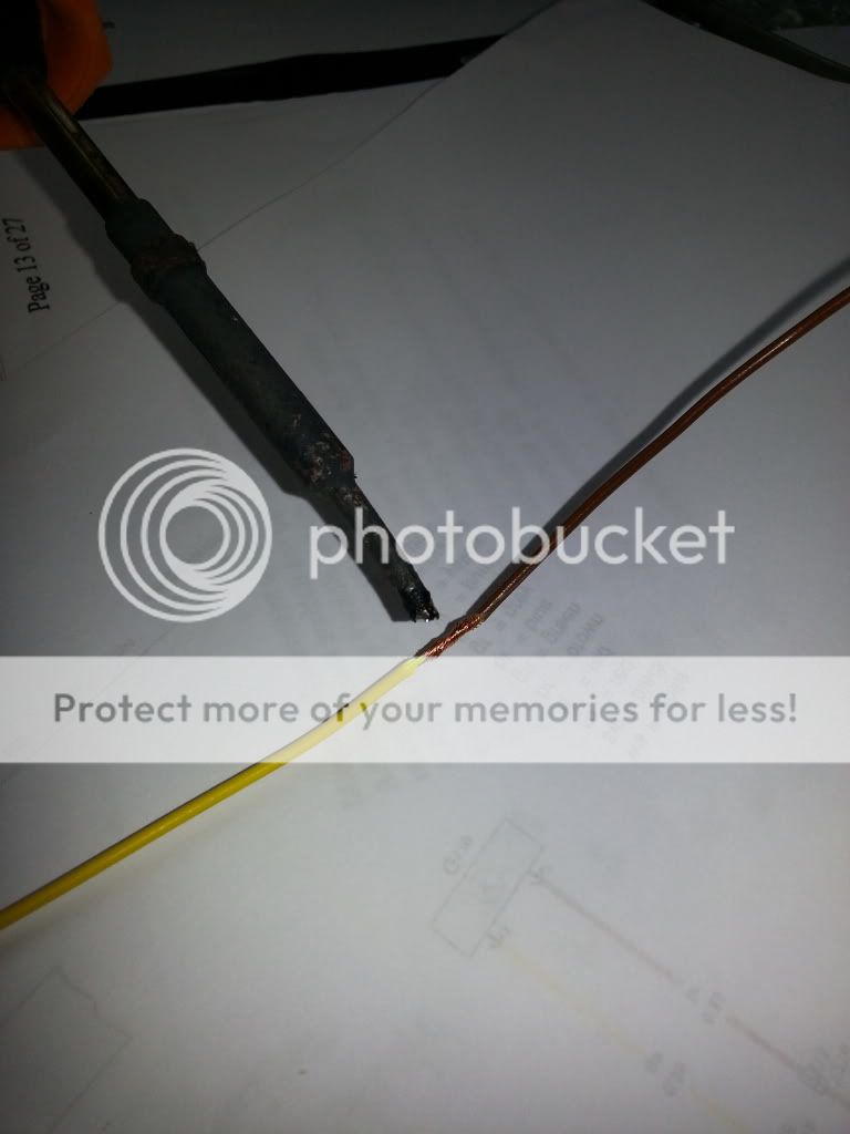
Locate the blue/black wire which is already inserted into the 16 pin plug at pin numbered 3. Splice into this wire and solder the other new wire from the new heated mirror glass to this blue black wire. Protect with heat shrink wrap and tape to the existing mirror wiring loom.

Reassemble the 16 pin plug and locate back into the door control module.
Refit everything in the reverse order and then the mirrors need to be coded with VCDS.
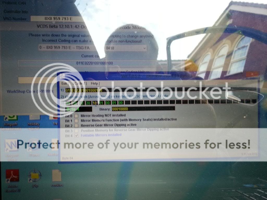
Un-check bit 0 in Byte 4 as shown in photo.
Once everything has been re-fitted , start engine, ensure mirror switch is in the centre position and warm your hands on the mirror glass!!
Hope the above has been helpful. The total cost for this is approx. £70 (The bulk of which is the mirror glass which may be cheaper). Allow 3-4 hours to do this, the first door will take the longest, the second one should be a lot easier after you've learned by your mistakes (as I did)!
Feed back welcome.
Cheers
Neil
My car is the A1 1.4 TFSI 185(PS) Black Edition. It is I believe a MY2012 edition.
It did not come with heated mirrors!
WARNING!! All modifications and changes are done at your own risk. I in no way approve or recommend the modifications performed here for your vehicle. Please check with your dealer or other competent person before performing any changes to your car as they may void portions of your factory warranty.
This âhow toâ is how I did it successfully, your car may be different and may have different part numbers and fittings. If you follow these instructions you do so at your own risk. I will not be held responsible for any damage done to your car should you follow this thread and damage your car. This is my story! Treat it purely as it is intended, a written record of what I did. Before prizing any plastic parts away from each other I suggest taping them up with masking tape to avoid unnecessary scratches and marks.
For info, the part numbers for my door control modules are:-
8X0 959 793 Dâ Drivers door
8X0 959 792 Dâ Passenger door
This info can be found by doing a VCDS scan
Tools required
T25 Torx Screwdriver
T10 Torx Screwdriver
10mm socket, wrench with extension bar
Small Phillips screwdriver
Small Slot Screwdriver
Medium Slot Screwdriver
Wire Cutters
Soldering Iron
Wide chisel
Masking tape
Cloth Tape
Cloth
VCDS
Parts
Left and right mirror glass with heating element. (Various mirrors available for approx £25-£30 each)
Yellow Repair wire (part number U000 979 009)
4 metres of thin wall wire
I used thinwall cable from:-
http://www.vehicle-wiring-products.eu/VWP-onlinestore/cable/thinwall.php
2 x 6mm female blade terminals like :-
http://www.vehicle-wiring-products.eu/VWP-onlinestore/terminalsnonins/noninsblades.php
Heat shrink from:-
http://www.vehicle-wiring-products.eu/VWP-onlinestore/sleeving/heatshrink.php
The retro-fit
Lower window down.
Ensure that ignition is off and remove key.
Both doors are essentially the same.
1. Remove Door card.
Gently prize off the speaker grill. On my car this was a blank. I applied masking tape to both the surround and the speaker grill to avoid damage to the plastic.
Then gently prize of the front piece of the door handle. Again cover both pieces with tape to avoid damage.
On removal of the speaker grill and door handle it will expose a Torx bolt behind each of them.
There are 4 Torx bolts to remove in all, numbered 1 â 4 in the photograph below. Use a T25 Torx bit.
You will then need to prize the door card away from the door itself. You may need to insert a chisel in between the door card and the door and lever it off until the poppers behind pop (as shown circled in yellow in the photograph shown a couple of steps below) or you might as I did manage to lever off with your fingers. If you use a chisel, wrap it in a cloth and use tape to avoid damage. Once the door card is off it will remain attached to the door by the cable operating the door handle opener and a wiring loom going direct to the door control module.
With regards to the cable for the door handle, prize off the blue clip, rotate the cable 90 degrees and lift it away. (Hard to explain but easy when seen).
The door control module
To separate the wiring loom from the door control module, lift the purple clip up (it will swivel) and then the light blue plug will lift away as the purple clip rotates.
The door card is now free. I placed it upside down and you can now see the 8 poppers circled in yellow which pop into the door in the picture above. These will likely break so it may be handy to buy some spares.
Next remove the plug that I have shown by a white spot on the photo above. (Although covered by the white spot, it can be seen clearly in prior photo. You will need to lift the red clip up first and then lever out. This is the 16 pin plug which I will refer to later and connects the wiring loom of the mirror to the door control module.
I decided to remove the whole wing mirror from the door. The cabling should be easily seen and followed between the mirror housing and the 16 pin plug. Remove this wire so that's its free all the way up to the mirror. Remove the three grommets from the door as shown in photo below:
Then pull out the large grommet where the wiring looms goes through.
Insert a 10mm socket on an extension bar into one of the 3 holes and remove the nut holding the mirror to the door. All 3 need doing in the separate holes. (this is why the window needs to be down).
There are some nylon ties holding the wiring loom inside the door which will need to be removed or cut. This was quite difficult to do, so I ended up cutting them. Be careful when removing the nuts as they are easy to drop into the inside of the door. You will then need to remove the large door speaker below to get them.
The mirror should then come away from the door. Feed the cable through the hole and remove mirror assembly away completely.
Remove the mirror glass from the mirror housing. Angle the mirror glass upwards, insert awide chisel in between mirror glass and mirror body (wrapped in a cloth) and prize mirror glass away. This needs a bit of force but be very careful. Too much force in a small area will crack the glass. You may be able to use yourfingers. It takes a bit of toing and froing, but the mirror glass will eventually come out.
Using a T10 Torx bit, unscrew the 4 screws holding the inner mirror body to the outer mirror body. Also undo and remove the screw in the centre of the mirror motor. All 4 screws and mirror motor screw are shown coloured by the 5 purple dots in the next photograph.
Insert afairly wide flat screw driver at the top of the mirror and twist the clips so that the inner mirror body and outer mirror body separate. You will also need to apply a pit of leverage between the two plastic bodies to ease them apart at the same time.
Feed two pieces of wire from the bottom of the mirror housing through the mirror body shown in the photo below. I used a coat hanger with the wires taped to the end (Don't go through the foam sponge, aim to go at the side). Push and wiggle until the coat hanger comes out the top above the spring shown. See pictures below.
Pull wire through mirror body, strip the ends of the wires and crimp onto the ends the two female spade connectors.
Re-assemble the mirror casing/body in the reverse way you took it apart. Push on the two female spade connectors onto your new heated mirror glass and then push and clip the mirror glass back into its housing. The two long (finger type) pieces of plastic need to be guided into the two âbronzeâ type oblong clip holders shown in the photos above. The mirror glass should just snap back into its clips. Apply even pressure and again be careful not to crack it.
Tape the two new wires to the remainder of the wiring loom all the way down to the 16 pin plug.
The 16 pin plug has inserts for 16 wires and these inserts are all numbered.
With a small flat headed screwdriver lift up the small clip on the side of the 16 pin plug gently and slide out the inner body.
A Picture of a repair wire is shown below on top of the wiring diagram for the mirrors. Ignore the purple/black writing in pencil, this is the colour of the wire found in the loom of a car with heated mirrors already.
Cut the repair wire in half and insert one end into the pin marked number 15 on the 16 pin plug. Solder the other end of this repair wire to one on the new wires going to the new heated mirror glass. Use heat shrink wrap to protect the soldered joint and tape this to the existing mirror wiring loom.
Locate the blue/black wire which is already inserted into the 16 pin plug at pin numbered 3. Splice into this wire and solder the other new wire from the new heated mirror glass to this blue black wire. Protect with heat shrink wrap and tape to the existing mirror wiring loom.
Reassemble the 16 pin plug and locate back into the door control module.
Refit everything in the reverse order and then the mirrors need to be coded with VCDS.
Un-check bit 0 in Byte 4 as shown in photo.
Once everything has been re-fitted , start engine, ensure mirror switch is in the centre position and warm your hands on the mirror glass!!
Hope the above has been helpful. The total cost for this is approx. £70 (The bulk of which is the mirror glass which may be cheaper). Allow 3-4 hours to do this, the first door will take the longest, the second one should be a lot easier after you've learned by your mistakes (as I did)!
Feed back welcome.
Cheers
Neil
Last edited:
